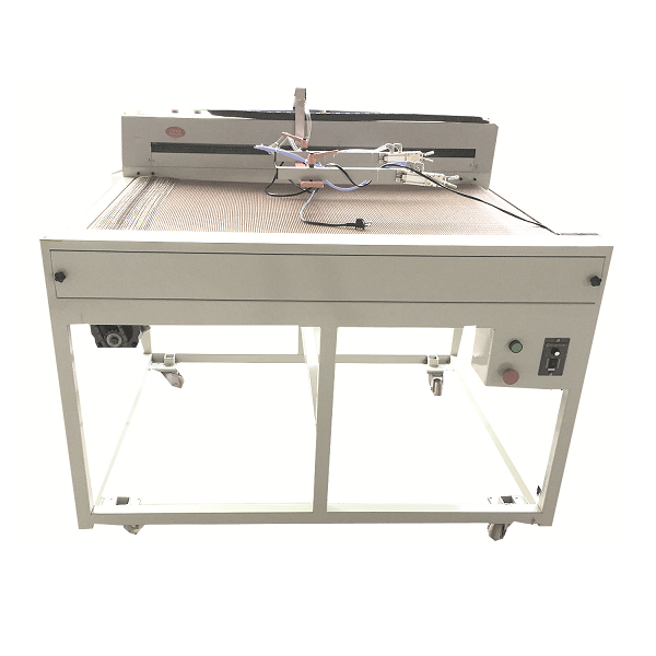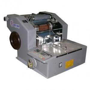
Semi-Auto Heat Transfer Screen Printing Line
SCREEN PRINTING MACHINE

Appendix
1. 1 Application Range:
The ZSA-1B machine is suitable for printing of paper, PCB, plastic, metal, glass and formed product.
1.2. Features:
1.2.1 Stainless steel worktable, front-back and right-left inching adjust, and process printing rapid and simple.
1.2.2 Three control methods can be selected: manual, single, automatic
1.2.3 In order to match with the Varity of ink and get different printing effect, the scraper and ink reclaiming slice can be controlled to stop at the right or left.
1.2.4 Adopting excellent electrical elements made by famous manufacturers, imported motor and PLC. High precision grinded linear guide guarantee smooth running and dura billity of the machine.
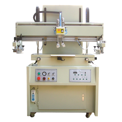
2. Specifications
|
1 |
Model | XH-6090 |
|
2 |
Max Printing Area | 600x900mm |
|
3 |
Worktable Dimension | 700x1000mm |
|
4 |
Max.Screen Frame | 1380x1100mm |
|
5 |
Thickness | 0-20mm |
|
6 |
Max.Printing speed | 13/min |
|
7 |
Air pressure | 3HP, 5.5-7.7kg/cm2 |
|
8 |
Power supply | 380V,2KW |
|
8 |
Overall Size | 1600mm*1060mm*1680mm |
|
9 |
Weight | 580 kg (about) |
|
10 |
Case Color | White/Blue |
We can customise other size for users. Customised size and weight pls adhere to the actural product instead.


3. Operation Panel Descriptions
- Power indicator
- Barometer for printing squeegee
- Printing Speed regulating knob
- The oil return speed regulating knob
- Printing count
- Second printing
- Operation mode
- Auto time display
- Automatic timing
- Ascending descending
- Oil return
- Scraping conversion
- Air suction mode
- Rapid oil return
- Printing
- ON/Off Furnace
- Scraper Pressure
- Safety valve
- Printing head
4. Installation and Test
4.1 The machine should be install in an environment of clear, and temperature keep in 18-28 degree.
4.2 Check fastener are well fit, and the moving part have lubrication oil after open the wooden box. Chose a well installation place for the machine, fit the 4 rubber to the legs, adjust it and keep the working table in horizontal. Ground wire should be connected to the machine.
4.3 Double color wire is ground wire, others are fire wire. After the wires were well connected. Press ‘Operation Mode’ to ‘Manual’.
Press ‘Air Suction Mode’ to ‘constant suction’.
Turn power on (see picture 1.4). Turn ‘Safety Valve’ on.
That will make the fan working. Put a lager surface paper on the working table, if the paper was sucked by the working table. It means the wires connection is correct. If the paper was blown by the wind, it means the power fire wire is opposite in phase, reverse any two of fire wire.
4.4 The air pressure for the machine is 5.5~7KG/cm2. If the air pressure lower than the number, pull out the adjustor, turn clockwise, make the air pressure increase. Turn counterclockwise will make the air pressure lower.
4.5 Press ‘Operation Mode’ to ‘manual’ control. Test the machine up and down, left and right movement.
Press ‘Scraping conversion’ button, test the scraper, and oil return scraper.
Caution: Could not do another operation, until all above working well. Otherwise, will damage the machine.
4.6 Finished above , following up Automatic and Single printing test.
4.6.1 Press ‘Operation mode’ to ‘Single’, step the foot pedal, then finished one time printing.
4.6.2 Press ‘Rapid Oil Return button’, Screen display

The movement is:
Down—Scraper left movement —-up, Scraper right movement
Could increase the printing efficiency.
4.6.3 Press ‘Second printing” ON, the movement is:
Down—Scraper Left movement — Right —- Left — Right — Up
Suitable for thicker ink printing.
4.6.4 Press ‘Operation mode’ to Automatic, adjust Timer Control KT(0~10S). The machine completed all the movement automatic. (Suitable for skillful worker, instead the Foot pedal )
4.6.5 Emergency Button
Emergency Button could lift up when the machine is running. Must step the Foot pedal to make the machine running after use the Emergency Button.
5. Operation describe
5.1.Install and Adjust Net Frame
Turn to ‘Offer Air’ (as picture1.35), make the Scraper up, loose the Net Frame Arm screw (as picture1.9). Adjust the Net Frame Arm in both side to suitable length (as picture2.25), install the Net Frame to the clamp then tight the screw. (as picture1.29). Completed installed, tight the screw. (as picture1.9)
5.2. Adjust the printing size.
Replace the printing scraper rubber to adjust the printing width according to your request. (as picture1.33).
Adjust the length of printing: Loose 2 screws (as picture1.11), adjust the left and right to suitable place. Tight the screw.
Printing and Oil return speed adjust (as picture3) ‘Printing Speed ’, to your suitable speed.
5.3.Follow below sequence to adjust the scraper and return oil knife.
a. Rotation: release 4 screws (as picture1.24) to adjust the rotation.
b. Parallelism: adjust 4 screws (as picture1.12) to keep the scraper and return oil knife parallel with Net Frame surface.
c. Speed: Adjust 4 screw (as picture1.12) on the right to control the lift speed of Scraper and oil return knife. Adjust ‘printing speed’ to control the speed of scraper.
d. Pressure for scraper: Adjust pressure valve (as picture1.39) to control the pressure of scraper (as picture1.38). Read the number from Barometer.
e. Pull the knob ‘printing head’ out (as picture 3.19), to unload the scraper and oil return knife. Installed the scraper and oil return knife press the ‘printing head’.
5.4. Adjust the height between Net Frame and worktable. (According to the thickness of workpiece) At the back of the machine, open the door.
Loose the screw. (see below photo) Turn the Rod to anti-clockwise direction to up, turn the Rod to clockwise direction to down.
Tight the screw.

| NO. | Name | NO. | Name |
|
1 |
Adapter for pedal switch |
22 |
Air Drum for scraper |
|
2 |
Universal wheel |
23 |
Ink Knife Lock Screw |
|
3 |
Power input |
24 |
Ink Knife Rotative adjustor |
|
4 |
Power Switch |
25 |
Arm of Net Frame |
|
5 |
Micro adjustor for Worktable |
26 |
Pillar for Lift Net Frame |
|
6 |
Worktable Lock Screw |
27 |
Speed Adjustor for Lift Net Frame |
|
7 |
Net Frame Rotative Adjustor |
28 |
Lift Net Frame Air Drum |
|
8 |
Net Frame Height Adjusted Screw |
29 |
Screw to Tighten the Net Frame |
|
9 |
Net Frame Left&Right Adjusted Screw |
30 |
Left & Right Net Frame |
|
10 |
Motor |
31 |
Work table |
|
11 |
Movement locker |
32 |
Hook for Ink Knife |
|
12 |
Scraper Speed Adjuster |
33 |
Scraper |
|
13 |
34 |
Ink Knife | |
|
14 |
Air Drum for scraper |
35 |
Air Drum for scraper |
|
15 |
36 |
Emergency Stop | |
|
16 |
Drag Chain |
37 |
Panel |
|
17 |
38 |
Scraper Barometer | |
|
18 |
Outer Shade |
39 |
Scraper Pressure Adjustor |
|
19 |
40 |
Electrical Box Door | |
|
20 |
Ink Return Knife Pressure Adjustor |
41 |
Foot Pedal |
|
21 |
Scraper Pressure Adjustor |

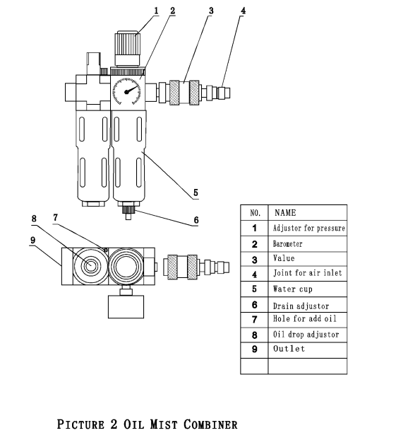
6. Maintenance:
6.1. Avoid the ink and organic solvent blocking the hole of suction on the worktable.
6.2. Drop little engine oil 10# on pillar every working shift.
6.3. The machine has Oil mist combiner (see picture 2).
6.4. Clean the Filter (as picture2.7). Offer the air, turn the drain knob (as picture2.8).
Wash the sponge in the water cup (as picture2.7) frequency. Take the Filter off, take out the sponge, leave few mins it in clear water, and dry it.
7. Attachment
1. Operation manual
2. Screwdriver 2 pcs, a 10’ Spanner, a hex Spanner, a Rob
3. 4 Rubber foot
4. Scraper and Ink return knife 350, 400

************************************************************************************************************************************************************************
POWDER COATING MACHINE
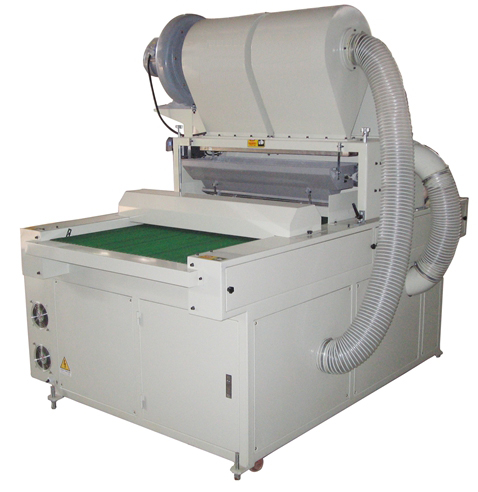
Brief description
After-printing corollary equipment which substitutes traditional handwork. This machine is convenient to apply, high effective, flexible, and free of contamination, which both increase productivity and raw material utilization, as well as producing beautiful pictures.
In this machine, parts for key position such as powder sucking, transducer are imported with the advantages of durable and stable. Especially, this machine works well with those have high requirement of paper, film, glitter, and hot melting powder. All the drives in this machine are infinite speed variation. If required, it can also connect with drying equipment and UV photo-cure equipment.
Main Technical Parameters:
| Model | Total Power | Width of Transmission Belt | Width of Powdering | Thickness of Paper | Overall Dimensions | Speed (Pcs/Hour) |
| ZSCT-II | 4.5KW | 1000(mm) | 900(mm) | 1—5(mm) | 2000*1700*2000 | 2000 |
Read manual carefully, before operate the machine. Do not adjust any of button before connect to electric power.
Operation Manual
Warmly reminder: The powder will not scattering until the film pass the sensor.

This machine is equipped with separated switches for both power sucking upward and downward, as well as switches for delivering, dusting, powder feeding, and electrostatic neutralizer.
Start-up procedure
- Switch on main power on the left case.
- Turn on the power switch (See picture II-2).
- Switch on upward power sucking motor (See picture II-8), and justify the frequency of transducer to 38-42HZ .
- Switch on downward power sucking motor (See picture II-11), and justify the frequency of transducer to 55-65HZ.
- Switch on the delivery power(See picture II-4), and adjust switch to 20-65HZ.
- Switch on the powder feeding adjustor (See picture II-15), and adjust switch to 20-65HZ.
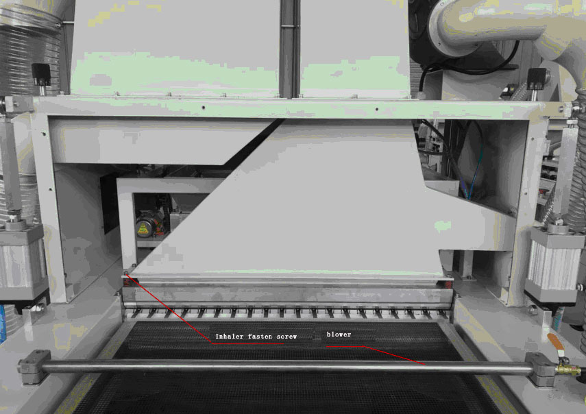
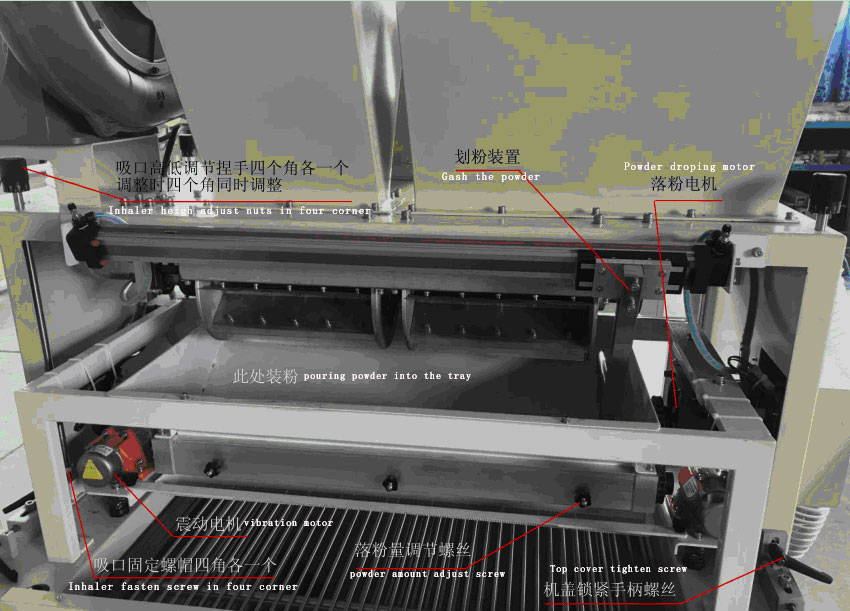
- Pour hot melting powder into the dust tray, and then switch on dusting motor (See picture II-17). First, adjusting the speed of dusting (the faster, the more powder). Or adjusting the three nuts under the dusting funnel (See picture I-4) to justify the amount of powder, so that to meet the product’s requirement for powder thickness and balance.
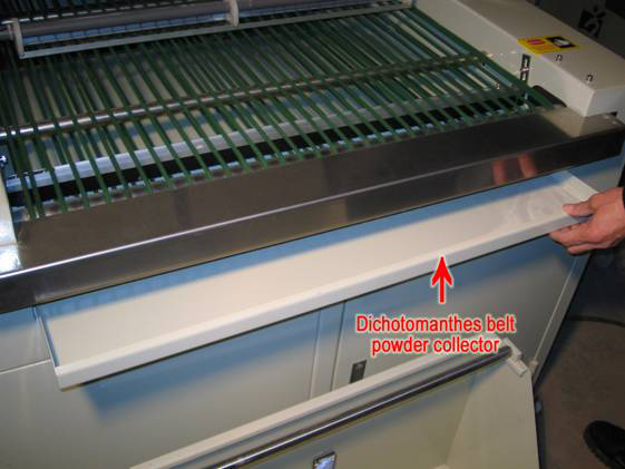
- Powder collector on the left case (See picture II-21) has the function of promoting powder-cycling. Usually, it is switched range from 60 to 70.
- Open the electrostatic neutralizer switch (See picture II‐13)
Adjust machine
1. Adjusting the space between powder sucking upward and downward to 2‐3mm.
If there is still gear wheel on the sample while operating (usually, it has been already adjusted before rollout), you can fine‐tune the height for power sucking upward to meet product’s requirement.
1.1 Release four nuts at the corner. Reminder: Adjust height only after release the four nuts. (See picture )
1.2 Release the nut (See picture 1), fine-tune the height for power sucking upward (See 1, 21,22). Or (See picture 1) Turn clockwise the gap getting close. Turn anticlockwise the gap getting wide.
1.3 Fine-turn four nuts at powder sucking area, make it balance. (See picture 1) Tighten the black screws (See picture 1)
Powder recycling process
1.If there is powder residue on the product, it is better to fine increase the speed of powder sucking upward motor (See picture Ⅱ-8). However, higher air flow can also cause paper jamming, adjust smoothly.
If there is still powder residue on product, after increase the speed of powder sucking upward, check the height of upward and downward. If the gap is too wide, follow the previous step to adjust the height.
Check the dusting bag without powder to block the air hole. According to the thickness of powder, it is necessary to clean the dust bag to avoid blocking up the air hole.
Check the bottom side of the machine, make sure the powder recycling assist system on.
Regulation of the amount of shaking powder
- Adjust the powder shake speed controller (See picture II‐22).
2. Adjust the powder shake speed controller (See picture II‐22) still not reach your demand. Could adjust the screw on the left of cage(See picture ).
Process for power off
- switch off the regulator of dust tray (see picture II -17)
- Shut down the regulator of shaking (see picture Ⅱ-22)
- shut down the switch of power sucking upward (see picture II-7)
- shut down the switch of power sucking downward (see picture II-10)
- shut down the switch of delivering (see picture II-4)
- switch of the switch of (see picture II-21)
- switch of the regulator of powder delivering (see picture Ⅱ-15)
- shut down the switch of main power (see picture II-2)
- Clean the control panel and cover it with dust jacket
Machine attendance
1. After operating for a period, open the baffle, and fill those active parts with 20# engine oil. If the chain is slack, use the elastic gear to adjust.
2. While replacing raw material such as glitter and hot melting powder, use compressed air to clean all these parts to avoid powder mixed.
3. According to the thickness of powder, it is necessary to clean the dust bag to avoid blocking up the air hole.
Operation empty machine
Turn switch on for machine rise (See picture 3). Turn the switch on the top half part of machine will rise up, otherwise come down.
Turn the delivery switch to automatic (See picture II-4), and shut down all other switch, make pre-heating film pass by.
Fault Resolution
1. Please replace speed governor while it doesn’t work.
2. Please follow the instruction in Machine attendance if the powder is not suck up completely as before. Or you can also increase destaticizer to deal with this problem.
3. Please check the powder whether they are clean and dry if dusting in difficulty. If the powder is wet, please insolating them under the sun.
4.If powder recycling tube block, Please check the bottom of the frame turn the residue assistant system on. Or Check the powder sucking downward, make sure it running.
5.Turn the switch on the top half part of machine will rise up.


************************************************************************************************************************************************************************
Manipulator